


")
")
")
")
")
")
")


This article discusses the official technical manual NO. 11-5855-263 · 10 of 1983 for night vision devices of two versions used in many NATO countries. The article does not display regulatory links. The article did not transfer applications from the original methodological guide. To reduce the amount of text to an acceptable state, duplicate information and charts were ignored.
DOCUMENT REGISTRATION NUMBERS
AN / AVS-6 (V) 1
(NSN-5855-01-138-4749)
AN / AVS-6 (V) 2
(NSN 5855-01-138-4748)
5 July 1983
A WARNING
EXPLOSION HAZARD
• Batteries used in this equipment contain pressurized sulfur dioxide gas.
• DO NOT heat, puncture, disassemble, short-circuit, attempt to recharge, or otherwise interfere with battery operation.
• Turn off the equipment if the battery compartment becomes excessively hot. If possible, wait until the batteries cool before removing them.
• Batteries have ventilation holes to prevent an explosion. When they release the gas, you will smell it (very caustic) or you will hear the sound of gas emitted. When the air vents are triggered, the batteries are reasonably safe from an explosion.
A WARNING
TOXIC MATERIALS
• The tube of the image intensifier in each monocular contains toxic materials.
• A broken tube can damage the binocular assembly, especially if the monocular body is physically damaged.
• If a tube defect occurs:
Do NOT inhale the phosphor material.
Do NOT allow fine phosphor material to enter the oral cavity or open wounds.
• If the phosphor screen material gets on your skin, immediately wash it with soap and water.
• In case of inhalation / ingestion of the phosphor material: induce vomiting.
After all procedures, you should immediately consult a doctor.
ERROR REPORTS AND RECOMMENDATIONS TO IMPROVE
You can help improve this guide. If you find any errors or if you know how to improve the system of the device, let us know. Mail your letter or form DA 2028 ("Recommendations for Improvement") directly to the commander. US Army Communications Command
ATTN: DRSEL-ME-MP, Fort Monmouth, New Jersey 07703.
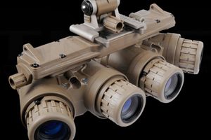
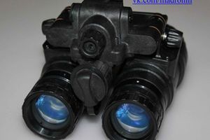
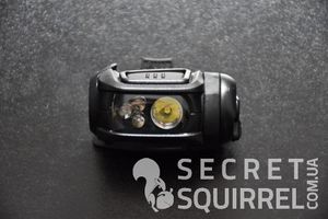
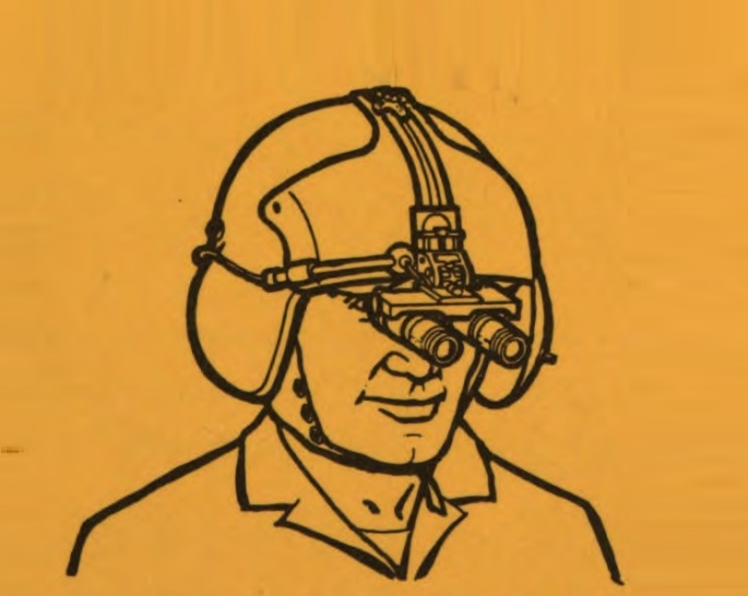
EQUIPMENT USED BY PILOT (Binocular Assembly)
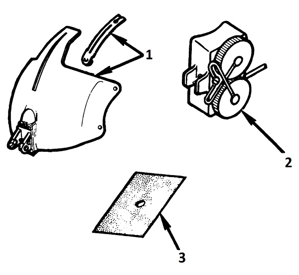
1-mount; 2-battery compartment; 3 velcro panel
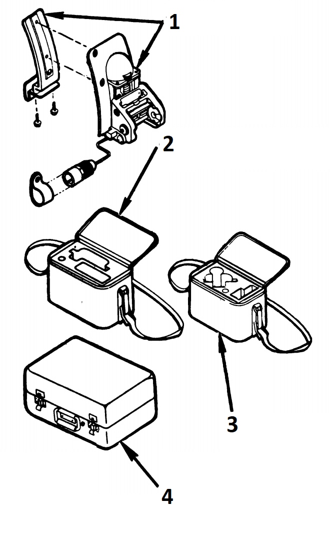
1-mount vertical adjustment binocular; 2- case for storing binoculars *; 3-case for storing a binocular under the helmet with an aiming system; 4 Shipping Case **
* BINOCULAR CABINET. Made of soft fabric material with foam inserts to protect the binocular and power supply when not in use.
** TRANSPORTATION CASE. Made of aluminum alloy. It consists of two sections connected by six button fasteners, which provide easy access to the contents. The case has a moisture-proof spacer. Two PU foam inserts protect the case during transport or storage.
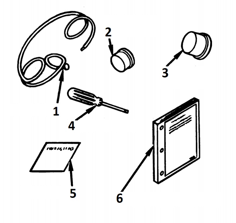
1-neck safety cord; 2-lens cap; 3-eyepiece cover; 4-screwdriver; 5 instructions for the care of lenses; 6-collection of guidelines
CHAPTER 1
INTRODUCTION
Section 1. GENERAL INFORMATION
1-1. GENERAL MAINTENANCE
Form of service. The department of military forms and procedures used for servicing equipment meets the requirements of ТМ 38-750. Army technical service management system (TAMMS).
Service. Provide a maintenance unit for the aviation unit (AVUM) every 6 months or after 100 hours of operation.
1-2. RECOMMENDATIONS ON TECHNICAL FAULTS OF EQUIPMENT
If your ANVIS needs repairs, let us know. Describe the nature of the equipment malfunction. Create an SF 368 form (Quality Report). Send the letter with the form by mail. Command of Communications and Electronics of the US Army. Fort Monmouth, ATN: DRSEL-M & .MP, Fort Monmouth, New Jersey, 07703.
1-3. REFERENCE INFORMATION
List of abbreviations and terminology. The terms (glossary) are used in this manual; see TM 11-5855-263-20 for instructions for maintenance of the aviation unit (AVUM).
but. List of terms used
Tilt-adjusting mount
Rotation axis adjustment
Tilt adjustments
Vertical adjustment pin
Hinge knot
Central rod and screw
b. Abbreviations
ANVIS - Aviator's Night Vision lmaging (Pilot's Night Vision Device)
AVUM - Aviation Unit Maintenance (Aviation Division Maintenance)
EIR - Equipment lmprovement Recommendation
mm - Millimeters
PAS - Pivot and Adjustment Shelf (Pan / Tilt Mount)
with. Glossary
BINOCULAR ASSEMBLY. Assembly, which is mounted to the mount. Contains two monoculars and a support shelf.
DARK. A place in which there is very little light. It does not matter total darkness. As a rule, this means conditions similar to the moon or starry night.
DARK-ADAPTED. Adapt the eye to the dark. As a rule, it takes about 15 minutes in a dark place to get used to the eyes.
EYEPIECE LENS ASSEMBLY (eyepiece block). It consists of an eyepiece lens and an eyepiece focusing ring. Attached to the back of the monocular case.
MOUNT. ANVIS protective cover, which replaces the standard SPH-4 protective cover. For use only with standard binocular assembly.
POWER PACKAGE MOUNT CONNECTOR. Connector (connector) between the power supply and the mount.
OBJECTIVE LENS ASSEMBLY. Consists of a lens module and a focus ring. Attached to the front of the monocular body.
POWER CONVERTER. An integral part of an aircraft that converts an aircraft's 28 V DC to 3.8 V DC for use by the ANVIS module.
POWER PACK Power Supply. Contains two lithium batteries. Attached to the back of the user's helmet.
Section 2. DESCRIPTION OF EQUIPMENT
1-4. CHARACTERISTICS, POSSIBILITIES AND FEATURES OF EQUIPMENT
but. Specifications.
• Uses available sky light to enhance night vision.
• Allows the pilot to use different flight modes at night.
b. Features and features.
• AN / AVS-6 (V) 1 attached directly to a standard SPH-4 flight helmet; an adjustable mount allows the AN / AVS-6 (V) 2 to be attached to the SPH-4 with an aiming system on the helmet.
• Battery or airplane powered.
• Focusing from 254 mm to infinity.
• Built-in low battery indicator.
• Binocular knot is adjustable by the distance between the eyes, vertically and tilted.
• Disconnects from the mount when the binocular is overloaded.
1-5. LOCATION AND DESCRIPTION OF MAIN COMPONENTS
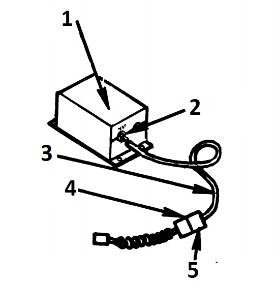
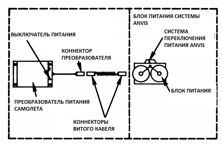
1 voltage converter *; 2 toggle switch; 3-power cable; 4-connector "dad"; 5-connector "mother"
*VOLTAGE TRANSFORMER. Used with ANVIS. Changes the power of 28 V DC to 3.8 V DC. Permanently attached to the aircraft. The kit includes a power cord with the inside of the quick disconnect and detachable twisted cord. Not part of ANVIS.
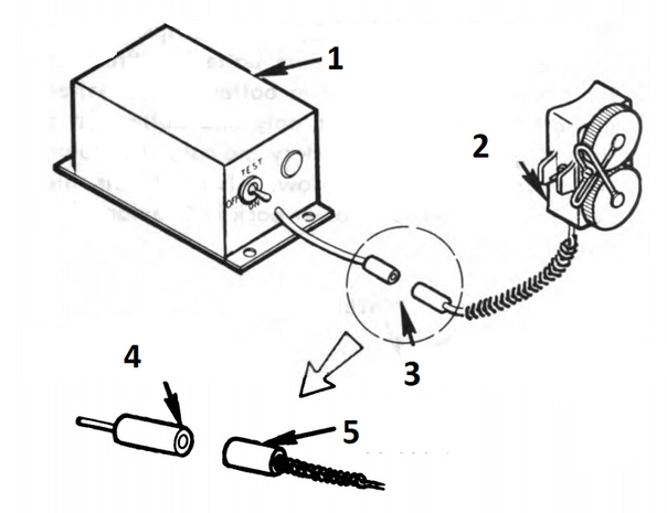
1 voltage converter; 2-battery box; 3-, quick coupling *; 4-connector type "mother"; 5 male connector
* QUICK CONNECTION. A simple jack-type connector that connects the power supply of the aircraft to the power supply. Allows you to quickly evacuate from the plane in an emergency.
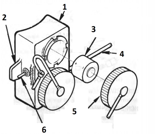
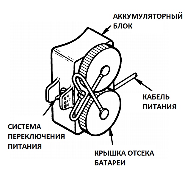
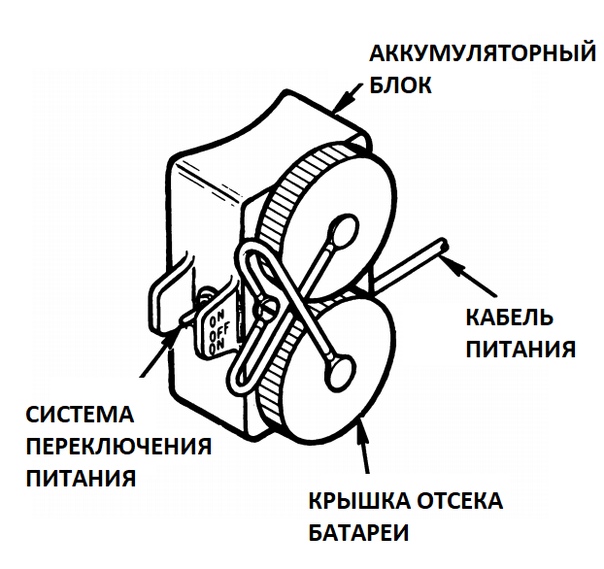
1-power unit *; 2-place installation of the counterpart Velcro panel; 3 lithium battery; 4-cable leading to the mount ANVIS; 5-battery cover; 6-system power on / off.
*POWER SUPPLY. Mounted on the Velcro panel of your helmet. Contains two lithium batteries. Provides automatic switching to battery power in the event of an aircraft power failure. Uses only one battery at a time. Low battery power indicator lights up. Also included is a system power switch.
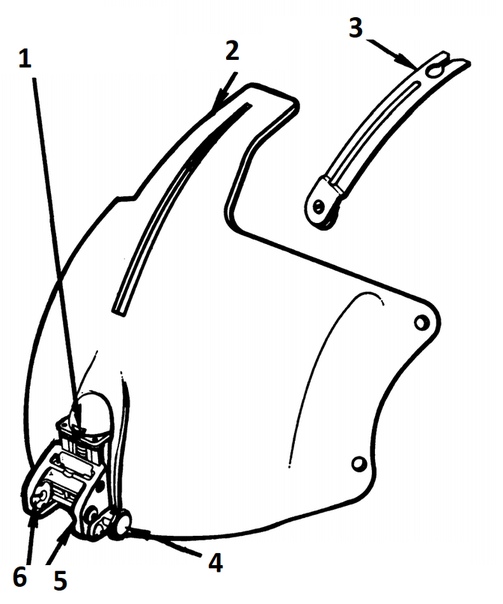
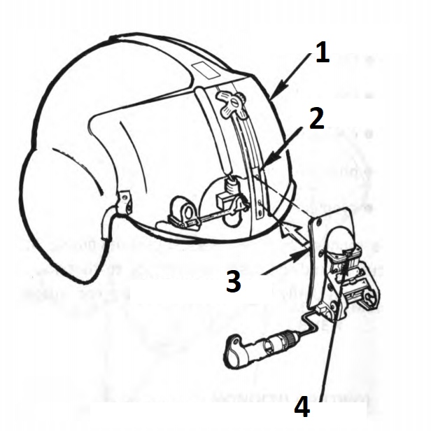
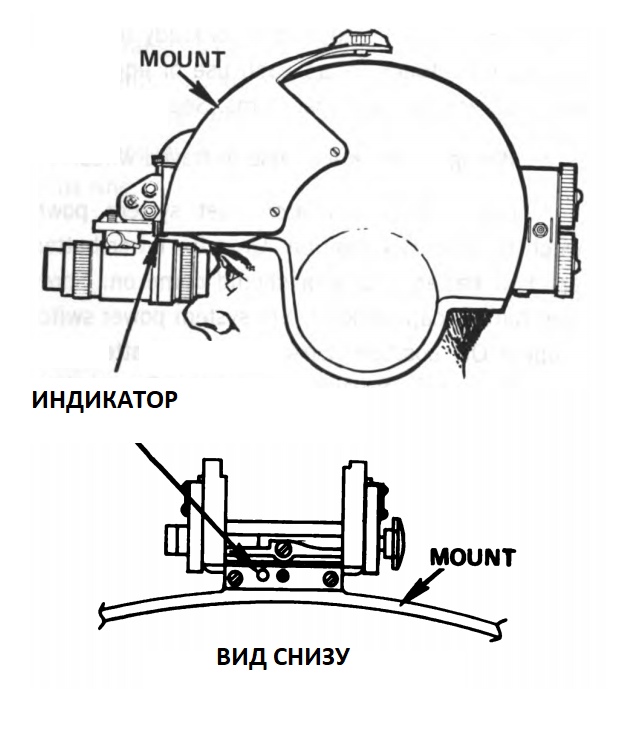
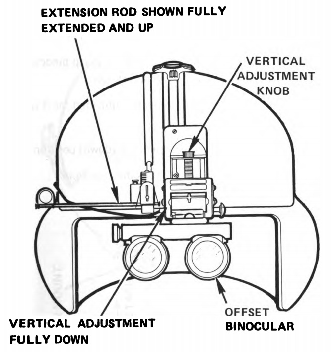
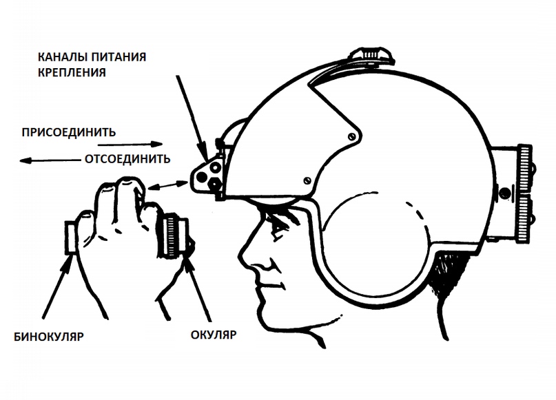
1-knob vertical adjustment; 2-mount ** on the SPH-4 helmet; 3-peak visor; 4- binocular extraction lever; 5- channel power supply NVD
* SPH-4. Personal pilot's helmet. Not part of the ANVIS system.
** SPH-4 MOUNT FOR ANVIS. Replaces the standard protective helmet SPH-4. Protects the visor from scratches and other negative effects. Contains channels for mounting the binocular to the helmet. It provides for tilting / lowering and adjustment of the vertical.
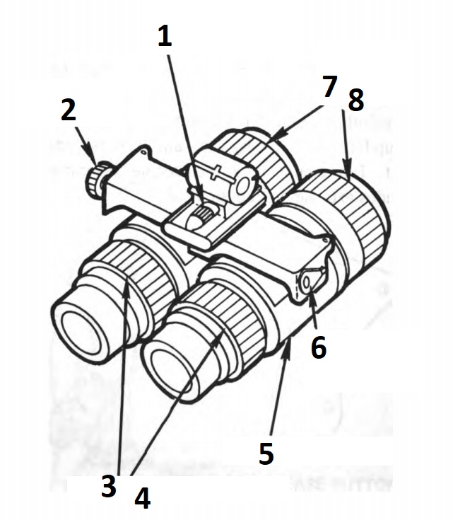
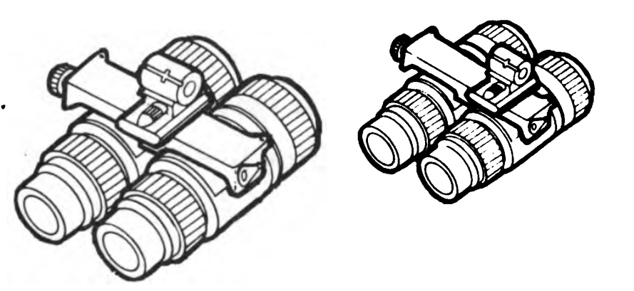
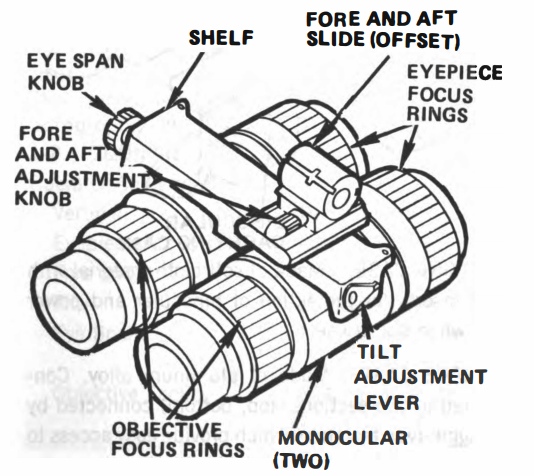
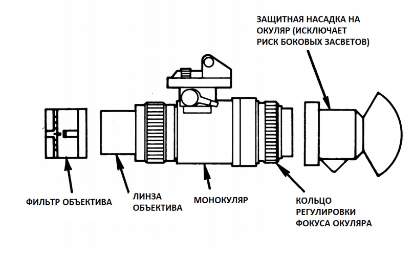
1-adjustment in the horizontal plane relative to the view of the operator; 2-adjustment of the collapse of monoculars; 3.4 focus setting; 5-pair of monoculars; 6-lever tilt adjustment.
ASSEMBLY AN / AVS-6 (V) l. Mounted and easily removed from the mount. Contains two monoculars and adjustments for:
• tilt
• forward and backward movement
• monocular collapse
• lens focusing
• focusing eyepiece
Monoculars collect incoming light, focus and increase its intensity so that you can observe a dimly lit scene. The environment is presented to you in a greenish color.
AN / AVS BINOCULAR ASSEMBLY 6 (V) 2. It contains the same settings and performs the same function as the standard binocular assembly AN / AVS-6 (V) l. The front slider is offset from the shelf for use with the SPH-4 helmet, modified by the sighting system.
1-helmet system aiming; 2 extension cord for mounting; 3-mount for AVS-6; 4-vertical adjustment of PVN.
AN / AVS 6 (V) 2 (the second version of AVS for working with helmets equipped with an aiming system)
1-6. EQUIPMENT DATA
Settings
Vertical: 19.5 mm
Eyepiece focus: +2 to -6 diopters
Adjustment forward and back: 15,8 mm
Tilt: 10 degrees
Eye camber: 21 mm
Lens focus: 254 mm
Electronics
Required voltage: 3.0 VDC nominal 400 mA, 100 mA
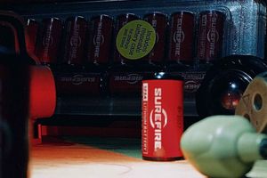
Battery Lithium (BA-5567 () / U): 16 hours of operation at a temperature of 23 ° C
Optics
Lens focusing range: from 254 mm to infinity
Eyepiece focusing range: + 2 / -6 diopters
Approximation: single approximation (1x)
Viewing angle: 40 °
Environmental conditions
Ambient temperature: from -32 ° C to 52 ° C
Lighting conditions: Cloudy, moonlight.
Section 3. TECHNICAL PRINCIPLES OF WORK
See chapter 2 section 1 DESCRIPTION, USE OF CONTROLS AND INDICATORS
CHAPTER 2
OPERATION INSTRUCTIONS
Section 1. DESCRIPTION, USE OF GOVERNING BODIES AND INDICATORS
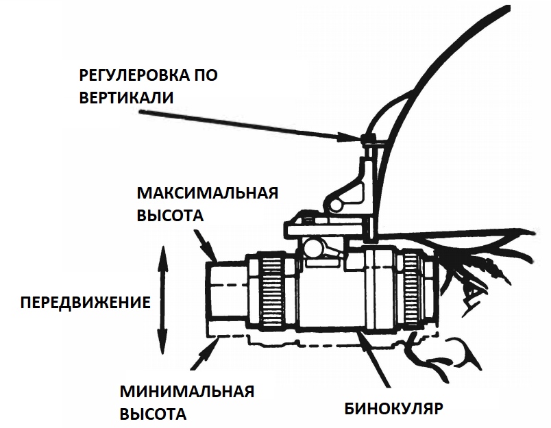
2-1. VERTICAL ADJUSTMENT
Binocular attachment moves up or down to fit the distance of the operator from the eyes to the helmet. Vertical movement is carried out by turning the adjustment knob vertically. The adjustment is self-locking.
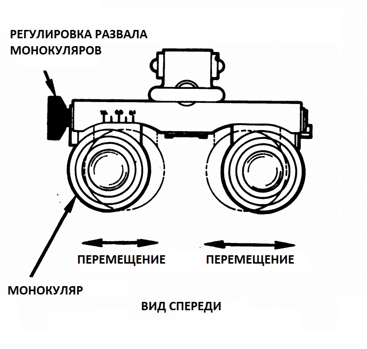
2-2. ADJUSTMENT OF THE MONOCULAR RANGE IN THE HORIZONTAL PLANE (CRUSH)
Allows you to move the monoculars to the sides to fit the distance between the eyes. Range adjustment is done by turning the range adjustment knob. The adjustment is self-locking.
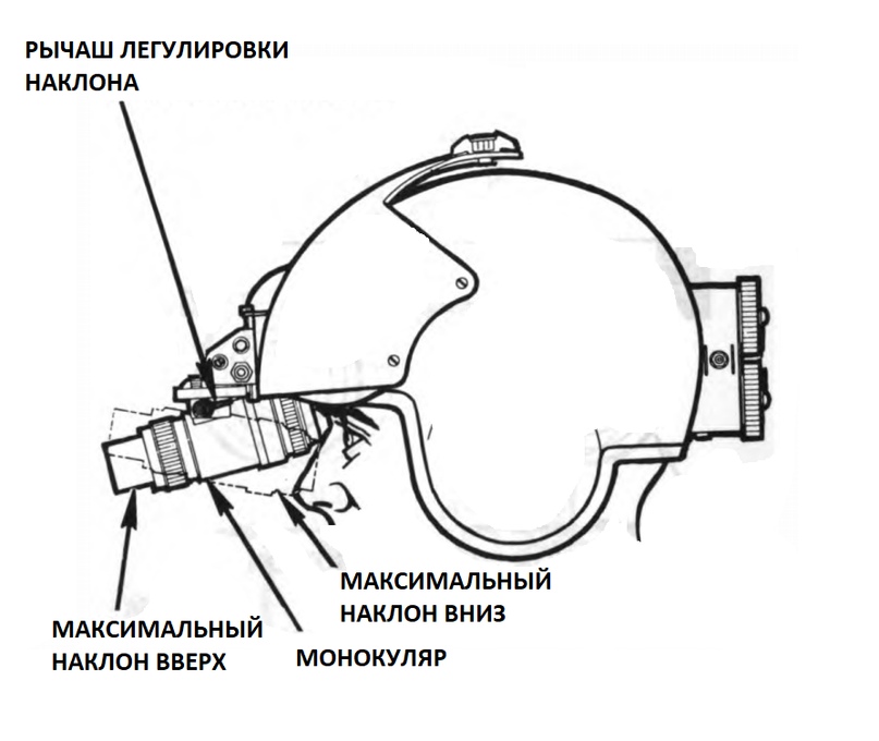
2-3. TILT ADJUSTMENT
Allows you to tilt the binocular. The tilt is performed by moving the tilt adjustment lever. This adjustment is self-locking.
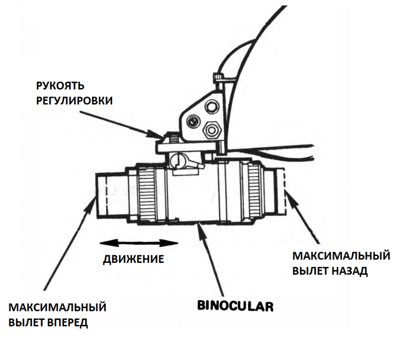
2-4. HANDLE ADJUSTMENTS IN THE HORIZONTAL PLANE RELATING TO THE VIEW
Allows monoculars to move back and forth to ensure a comfortable distance of the night vision device to the eyes. This adjustment is self-locking.
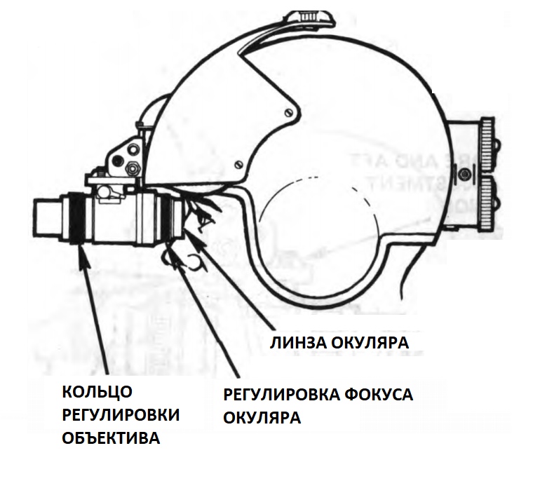
2-5. RING FOCUSING OCULAR AND LENS
The eyepiece ring allows the operator to move the eyepiece in and out to get a clear image. Adjustable from +2 to -5 diopters. The lens ring allows the operator to move the lens in and out for a clear view of images ranging from 254 mm to infinity.
2-6. POWER SWITCHING SYSTEM
The switch is located on the power supply. Three switch positions: ON / OFF / ON. The three-position toggle switch allows you to switch between ANVIS batteries. Latching the toggle switch to ON provides power to the connectors for attaching the night vision device. When you connect the power of the aircraft, the power from the battery is automatically turned off. The OFF position cuts off both types of power supply.
2-7. LOW CHARGE BATTERY INDICATOR
The LED lights up with a dim red light in your field of view when there is about 30 minutes of active work left in the battery.
Section 2. CHECK BEFORE OPERATION
2-8. CHECK BEFORE OPERATION
but. Basic checks. These checks help the ANVIS operator determine if its equipment is ready for operation. Perform these before each use of the equipment. Report defects using the correct forms.
s Check wiring. Check for loose or frayed wires.
with. Low battery indicator. Set the system power switch to the lower ON position. Unscrew the bottom cover of the battery. The low battery indicator should light up. Lock the bottom battery cover back. Set the system power switch to the upper 0N position. Unscrew the top cover. The indicator must be activated. Set the power system switch to 0FF.
D. Lenses. Check the lens and eyepiece lenses for dirt, dust, fingerprints, scratches, chips or cracks. Inspect the lenses if necessary.
e. Contact binoculars. Check double contacts for dirt and wear. Send to AVUM if there are damages that cannot be repaired.
e. Adjustment. Move the settings throughout the range to ensure their free movement. Adjustments include a vertical adjustment knob, a length adjustment knob, a horizontal adjustment knob relative to the view, a tilt adjustment, an eyepiece focus ring, and a lens focus ring.
Section 3. OPERATION
2-9. PREPARATION FOR USE OF STANDARD FIXING
The AN / AVS-6 (V) 1 and AN / AVS-B (V) 2 system consists of a transport and storage container containing the following:
• mount
• case
Open the transport and storage case and make sure that all parts are in place. Remove the canvas cover and make sure that it contains the following details:
• binocular assembly
• Power Supply
• screwdriver
• manual
• package with lens, paper
• neck cord
• Velcro panel.
2-10. INSTALLATION OR REPLACEMENT OF FASTENINGS OF NVD
• This procedure is for standard mounting only.
• Use a flat surface to install or replace the NVD mount.
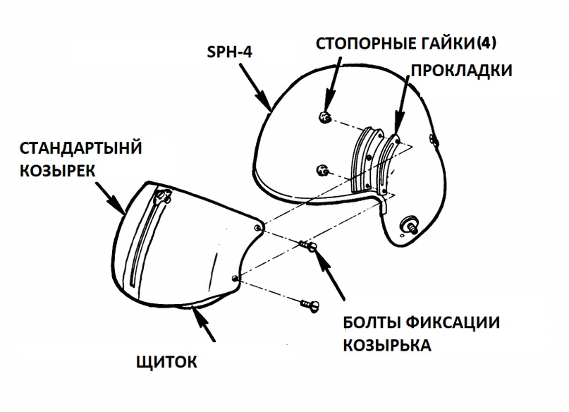
Step 1. Use the screwdriver supplied with the ANVIS; Remove all four mounting screws from the SPH-4 shield. Set the screws aside.
Note
• If there is adhesive tape, fasten the nuts on the inside of the helmet.
• If the lock nuts fall out of the helmet, set them aside.
Step 2. Remove and set aside two gaskets. if the gaskets are not removed, leave them.
Step 3. Remove the SPH-4 shield guard and the protective shield from the helmet.
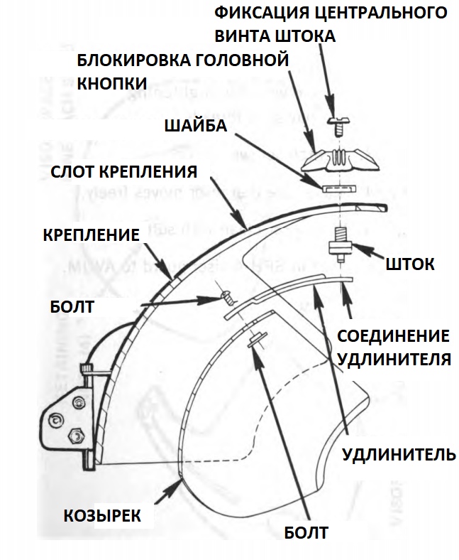
Step 4. Use a screwdriver from the carrying case; unscrew the center screw stem from the SPH-4 by turning it counterclockwise.
Step 5. At the hand, unscrew the lock of the unlock button.
Step 6. Lift up the stem lock washer
Step 7. Turn the stem ¼-turn and pull it out of the slots in the protective cover.
Step 8. Detach the visor from the SPH-4 shield.
Step 9. Remove the screw and nut from the extension
Step 10. Insert the nut into the groove of the visor. Put the extension on the nut. Insert the screw.
Step 11. Gently tighten the screw to avoid overtightening.
Step 12. Place the stem through the slots in the extension and secure.
Step 13. Place the lock washer on the stem.
Step 14. Manually, screw the lock release nut to the stem.
Step 15. Use a screwdriver to tighten the stem lock nut counterclockwise.
Step 16. Block the visor in the upper position.
Step 17. Secure the gasket screws with the visor fixing bolts
Step 18. Secure the visor line and the mount with the helmet guides.
Step 19. Slide the mount to align the screw holes.
Step 20. Insert the mounting screws through the holes in the mount and through the holes in the gaskets and the helmet. Keep the fastening nuts inside the helmet.
Step 21. Tighten the screws with the mounting nuts.
Step 22. Tighten all four screws.
ATTENTION
Do not overtighten the screws. Excessive tightening may cause the screw connection to break.
Step 23. Tighten the screws.
Step 24. Make sure the visor moves freely.
Step 25. Wipe the visor with a clean, soft cloth.
Step 26. Rotate the SPH-4 faceplate to its working position.
2-11. PREPARATION FOR THE USE OF FASTENING COMPATIBLE WITH THE SPH-4 HELMET HEATING SYSTEM
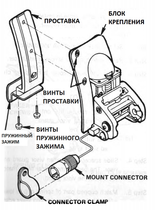
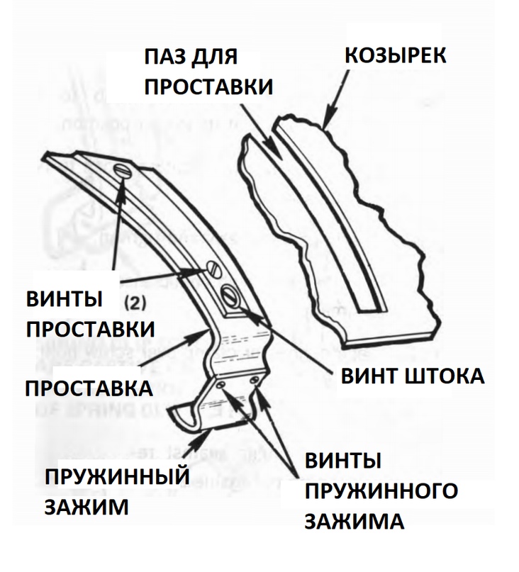
The mount consists of:
• Spacer
• Spacer Screws (2)
• Spring clamp
• Spring clip screws (2)
• Lock screw
• AVS-6 mounting block
• Power connector clip
Attaching the spring clamp screws, the spring clamp itself and the locking screw attached to the spacer are attached to the AVS-6 mount.
NOTE
Use a flat surface to install or replace the mount.
Step 1. Install and lock the visor up.
Step 2. Remove both spacer screws from the spacer.
Step H. Loosen (do not remove) the two screws of the spring clip
NOTE
The mount fits into an existing SPH-4 helmet protective shield modified with an aiming system mounted on the helmet.
Step 4. Insert the spacer up between the protective shield and the visor. The overlay on the spacer should coincide with the slot in the protective casing.
Step 5. Align the cup-shaped part of the spring clip with the bottom edge of the helmet. Press the spring down until it clicks.
Step 6. Tighten the rod screw until the gasket on the spacer is almost flush with the slot in the protective casing. Do not overtighten the screw.
Step 7. Tighten both spring clip screws.
Step 8. Turn the vertical adjustment knob to set the mounting washer to its lowest position.
Step 9. Align the two holes of the AVS mount block with the two holes in the spacer.
Step 10. Insert spacer screws and tighten. Do not overtighten the screws.
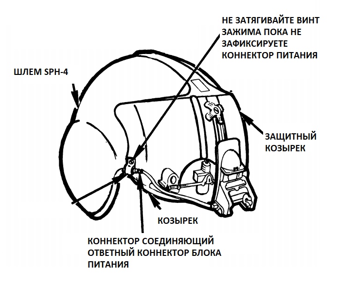
Step 11. Remove the lower right screw securing the protective shield.
Step 12. Align the power connector clamp with the screw hole.
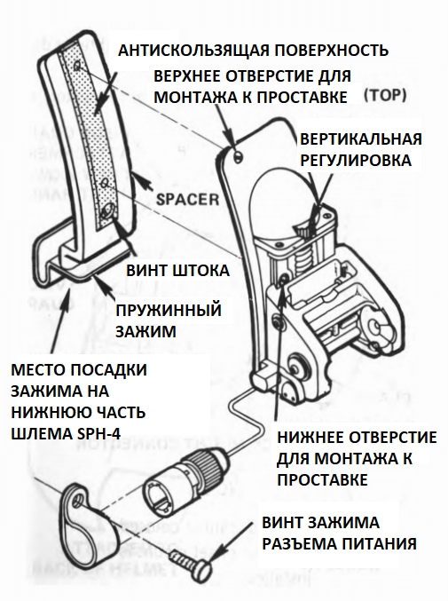
Step 13. Attach the clip to the visor, without tightening the clamp screw to the end.
Step 14. Insert the power supply connector into the clip.
Step 15. Tighten the clamp screw
Front view of ANVIS-6 version 2
2-12. INSTALLATION VELKRO PANELS
NOTE
Make sure the back of the helmet is clean.
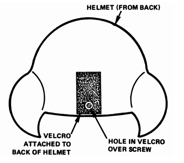
Step 1. Remove the protective film from the velcro.
Step 2. Center and attach to the back of the helmet. If necessary, install a screw with a washer to secure the Velcro panel more securely.
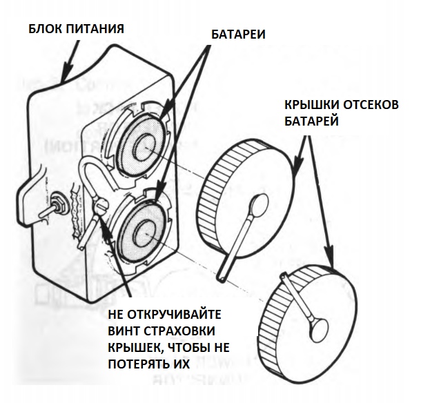
2-13. POWER SUPPLY ASSEMBLY
ATTENTION
Keep battery polarity.
Step 1. Push and turn the battery covers counter-clockwise.
Step 2. Install the batteries.
Step 3. Push and turn the battery covers clockwise.
2-14. INSTALLING THE HEAD SUPPLY UNIT
Step 1. Attach the Velcro mating to the back of the power supply.
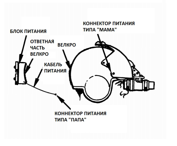
ATTENTION
Make sure the power switch is set to OFF.
Step 2. Attach the power supply connector to the AVS-6 mount connector
2-15. INSPECTION OF LOW CHARGE BATTERY INDICATOR
Step 1. Disconnect the power supply connector. Set the system power switch to the lower ON position.
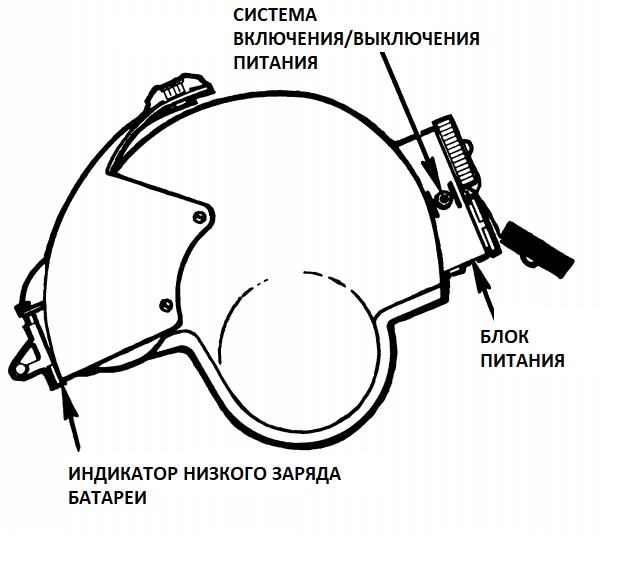
Step 2. Turn off the bottom cover. The low battery indicator should come to active mode. If not, replace the battery. Check the power supply connector. If the indicator is still not active, replace the power supply.
Step 3. Set the power switch to the upper position ON.
Step 4. Repeat step 3 with the top battery. If the indicator is not active, replace the battery or power supply.
Step 5. If the indicator is active in both cases, set the power system to OFF.
2-16. CONNECTING THE POWER SUPPLY TO THE CONVERTER FROM PLANE POWER
Step 1. Make sure the inverter is turned off. Place the ANVIS power supply switching system in the ON stage.
Step 2. Insert the first part of the twisted cord into the converter connector, and connect the second part with the aircraft power system.
Step 3. Press and hold the power converter switch in the TEST position. The control indicator should go to the active phase if the power converter is in good condition. If the test indicator does not turn on, the power converter is faulty. Notify aircraft maintenance personnel of a malfunction.
Step 4. Set the aircraft's power converter switch to ON.
Step 5. Set the ANVIS power switch to OFF.
2-14. FIXING BINOCULAR TO ANVIS FASTENING
• Ensure the ANVIS power system is turned off.
• With the helmet on, put the binocular lens on the eyepiece with you.
• Secure the binocular securely in the power channels provided for it in the mount.
• Turn the binoculars to the working (down) position.
ATTENTION
To avoid damage to the image amplifier tubes, use binoculars only at night. Do not turn on the device during daylight hours without protective filters.
!ATTENTION!
The low battery indicator indicates that the binocular is powered by a weak battery with less than 30 minutes power. The power supply has an alternative battery. Set the power supply switch to another battery. If the low battery indicator goes out, this is a signal that power is being supplied from a more full battery. The low battery indicator also goes out if power is connected to the aircraft.
2-15. CHECK AVS-6 CORRECTIONS
ATTENTION
Make a check in a dark room.
To check shading, sidelight, bright spots, blinking, flickering, or intermittent operation, check the binocular as follows:
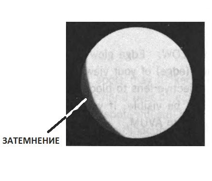
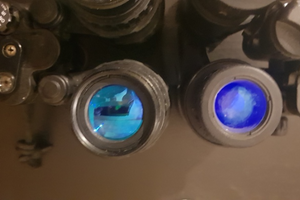
An example of a faulty monocular. The fault is caused by a darkening in the lower left of the image circle.
SHADING. If shading is present, you will not see a completely round image. Shading always starts at the edge and moves inward. If you see the shading, turn it in AVUM
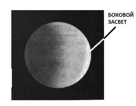
LATERAL COLOR is a bright area on the outside of the image area. Bring your hand to the lens to extinguish the whole world. If you see a side light, send in a binocular to AVUM.
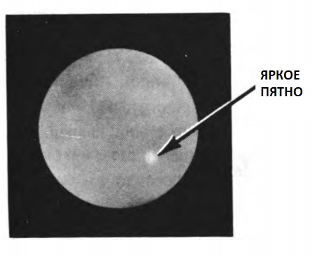
BRIGHT SPOT. Bright spots may flicker or may be static. Bring your hand to the lens of the lens, extinguishing all the light. If you see bright spots, contact AVUM.
ATTENTION
Make sure that bright spots or highlights are not caused by the light source in the scene. Ensure that shading is not the result of improper tilt, monocular collapse, or vertical settings.
ATTENTION
USE BINOCULAR EXCLUSIVELY TOGETHER WITH THE INSURANCE NECK CORD TO PREVENT DYNAMIC DAMAGE TO THE BINOCULAR DURING EMERGENCY DISCONTINMENT OF FASTENING
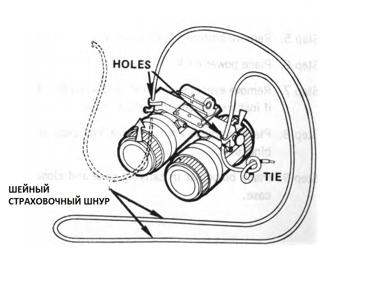
Example of the installation of a safety cord
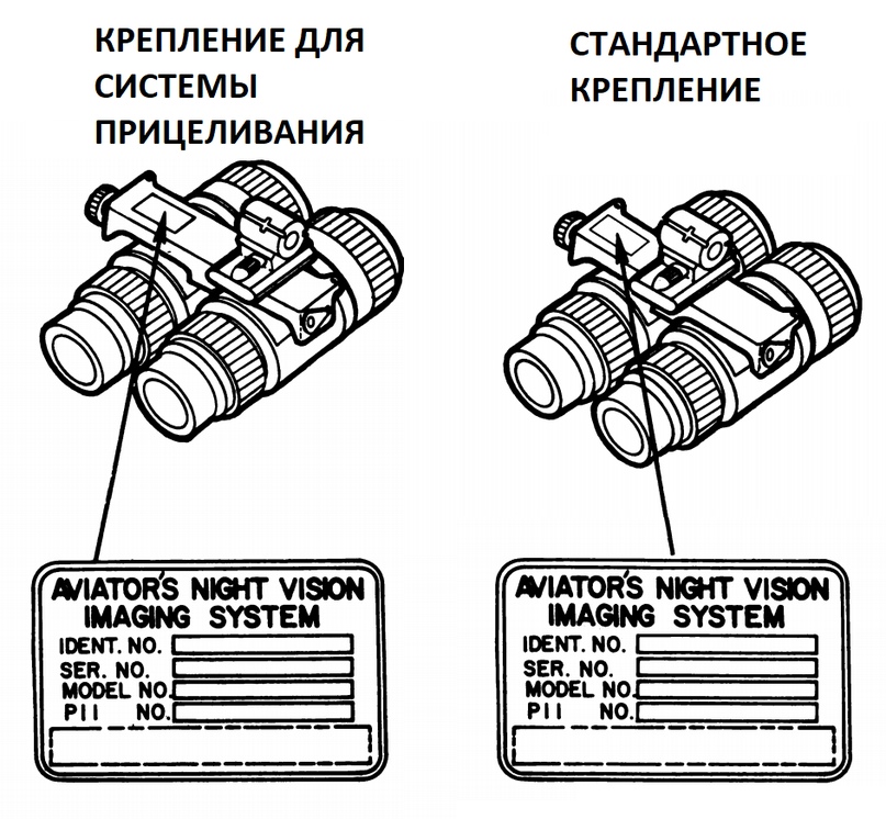
2-16. IDENTIFICATION PLATES
Author: GLAVIN ANTON JAEGRKORPSET AIRSOFT